2024.01.31.

A Freyssinet korszerű megerősítési technológiái adtak új távlatokat egy régi hídnak Vietnámban. Kollégáink megosztották velünk tapasztalataikat a projektről és rögtön arra gondoltunk, hogy sok magyarországi hidat ismerünk, melyek megértek egy hasonló felújításra.
A Kenh-Te híd a több mint 9 milliós lakosságú Ho Chi Minh város egyik legforgalmasabb hídja. A helyi hatóságok a pálya szélesítése, a növekvő terhelés és a földrengésnek való megfeleltetés érdekében megbízta a Freyssinet Vietnam-i vállalatát a szerkezet bővítésének és megerősítésénak feladatával. Kiemelt elvárás és kihívás volt a fenti igények kielégítése mellett, a közúti forgalom fenntartásának biztosítása és annak lehető legkisebb zavarása.
A feladatot kollégáink nagyszerű megoldásokkal oldották meg, felhasználva cégünk több utófeszítési és szénszálas megerősítési technológiáját is.
Located over the Kênh-Té (Kenh-Te) canal, connecting the dynamic and growing 7th and 4th districts of Ho Chi Minh City in the south of Vietnam, Kenh-Te Bridge is one of the busiest bridges of the city. It is for that reason that the Ho Chi Minh City Department of transportation, Urban traffic management Division N°1, the owner, have selected Freyssinet Vietnam to perform the widening works of the bridge. As one of the busiest arteries of the city, closing the bridge during the widening works was not an option, leading to very complex widening staging in order to ensure as minimum disturbance as possible.
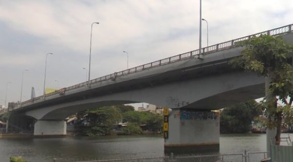
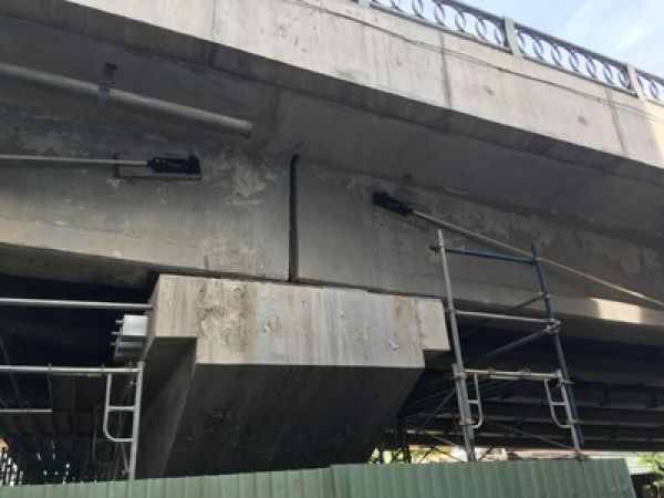
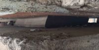
Meglévő híd
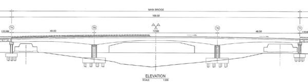
Hosszmetszet
The Kenh-Te Bridge is divided into 3 sections : 2 approaches and one main bridge.
The approaches are made of simply supported spans, 33m each and each approach has 4 spans. Each span has 6 prefabricated prestressed concrete I-girders with a cast-in-place concrete slab acting as a link slab at the support location.
The main bridge is cast-in-place, 3 webs box girder, having one main span of 72 meters and two end spans of 48 meters each. The box girder’s height is variable, going from 1.96m at mid-span to 4 meters at support location. Cantilever and external continuity PT are provided without any transverse PT.
The client has requested the widening of the road way from 2*3m lanes to 2*3.5m lanes is each direction. The increase of 16% of the roadway allows, in this city, were a high portion of the traffic is constituted of 2 wheels vehicles a significant reduction of the congestion on the bridge.
In addition, the bridge is requested to be compliant with the TCNV, the local design specifications of highway bridges design. This includes the HL93 load specifications and the most updated seismic requirements.
The strengthening and widening solution included additional external PT for both approaches and main bridge, shotcrete strengthening, transverse carbon rod and additional seismic buffers.
All the works were done under reduced traffic and several shifts in order to ensure the quick execution of the works and the minimum disturbance.
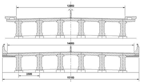
Híd pályalemez elrendezés szélesítés után
Widening of the approaches
The approaches are composed of 4 spans of 33m. A span is composed of 6 precast prestressed girders simply supported at their ends. Precast slabs of 8cm are installed between the girders and a top cast-in-place concrete deck of 20cm is poured at the top of the structure. The spans are made continuous in the longitudinal direction through the concrete deck.
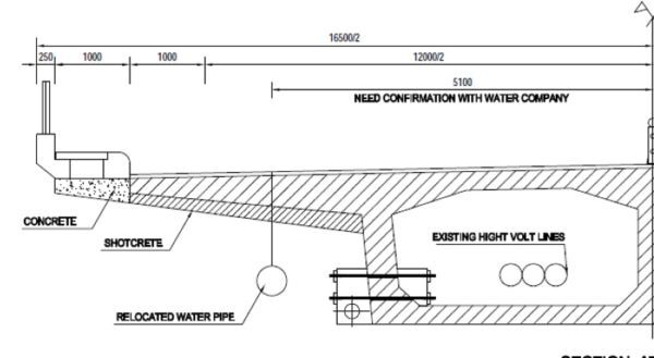
The transverse section of the approaches before and after widening is giving in the figures below.
Felhajtó hidak pályaszélesítés előtt és után
The retrofitting of the approaches included:
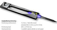
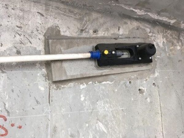
- A longitudinal retrofitting using external prestressing deviated by metallic parts installed below the soffit of the bridge
- A transversal retrofitting composed of carbon rods and shotcrete
- The replacement of the existing bearings following the inspections on site to create a base isolation of the structure.
 Additional prestressing was required to respect the service conditions of the bridge in the longitudinal direction. As a matter of fact, the exterior girder of the approaches undergoes an increase of the permanent and service load due to the presence of shotcrete and the more eccentric live load.
Thus, two 1R15® anchorages were installed on the side of the exterior girders. The strands are deviated in the bottom part of the girder by metallic deviators.
This design solution offers a quick and easy solution to install for the construction site.
The longitudinal view of the additional PT layout is shown below; Special care was taken to ensure the PT bar drilling through the deck beam doesn’t conflict with the existing PT.
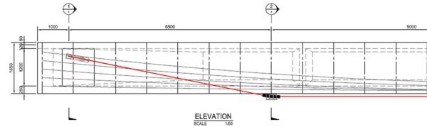
Kiegészítő hosszirányú megerősítés egy tartó külső oldalán
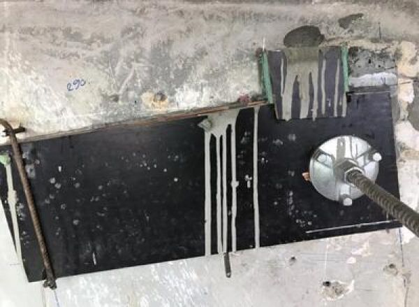
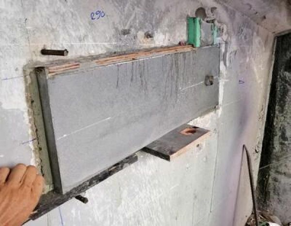
Transverse retrofitting
Due to the increase of loads on the cantilever wing of the deck slab, strengthening in the transverse direction was required. The strengthening solution consisted on adding a bottom shotcrete layer (in green) to increase the capacity of the existing rebar. In addition, d12 carbon rods Foreva© RFC12 were embedded in the upper face of the top slab.
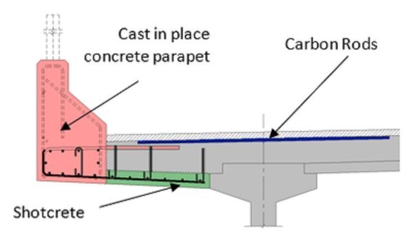
Keresztirányú megerősítés séma
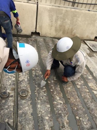
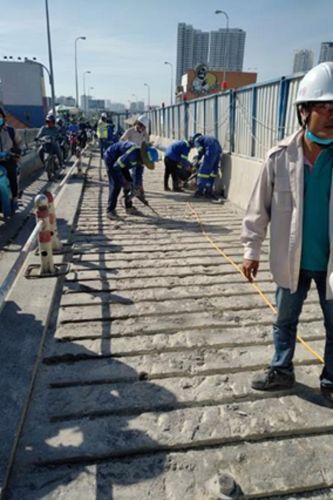
After being cleaned, the Foreva© RFC rods are coated with an epoxy layer and then rolled into sand in order to increase the surface roughness and thus the bonding capacity. They are afterward installed in 24mm*24mm groove, spaced by 250mm and embedded using adequate mortar. The use of mortar was privileged to the use of epoxy for groove embedment as epoxy’s behaviour after the application of the hot asphaltic cover will not allow to guaranty the proper function of the Foreva© RFC strengthening.
The girders laid on basic elastomeric pads of 400*250*50mm. In the horizontal direction, the restrain conditions of the 4 spans of the approaches were as follows
- Blocked in the longitudinal direction at M1 using φ75mm rebars anchored in the abutment,
- Free to move in the longitudinal direction at T1, T2, T3 and T4. Theses boundary conditions were created via φ75mm rebars in oblong holes in the longitudinal direction on piers T1, T2, T3 and T4.
- Blocked in the transversal direction at all piers
After inspection of the bridge, it appeared that irreversible deformations in the longitudinal direction of the bridge forced the bearings to displace and the pins to be in contact with the substructure at both ends of the approaches. The site observations that were confirm through calculation model, generated additional permanent efforts in the substructures and pre-loaded the seismic pins that were not guaranteed to function properly thru a seismic event.
Keeping in mind the objective to prevent retrofitting the foundations (which is often a costly operation), it has been chosen to remove all steel pins and to provide a new base isolation to the deck structure by replacing the existing elastomeric pads by ISOSISM® HDRB (High Damping Rubber Bearing).
Thanks to the high damping (ξ=16%) the efforts in the case of seismic event is reduced by approximately 50% and there is no need to retrofit the foundation.
As Kenh Te bridge is located in Ho Chi Minh City urban area, many pedestrians use this bridge. Deletion of sidewalks after widening was not conceivable as pedestrians would have been compelled to large detours. Therefore, on the contrary to the approaches, the walkways were required to stay on the Main Bridge.
In order to meet these two conditions, the sidewalks needed to be shifted from their existing locations by 1 meter outwards. Therefore, deck top slab must have been widened as follows:
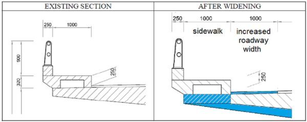
Gyalogjárda konzol kialakítás szélesítése előtt és után
This new deck top slab layout led to an increase of bending moment in the overhang due to:
- The additional dead weight of widened deck,
- The increase by 1 meter of lever arm of the live loads, especially truck wheels.
It also led to an increase of longitudinal efforts in the deck due to:
- The additional dead weight of widened deck,
- The increase of live load capacity of the bridge.
Strengthening and upgrading were therefore needed for the bridge to remain compliant with the latest relevant Vietnamese standards.
Freyssinet designed and implemented a strengthening solution including external post-tensioning, carbon rods, shotcrete and seismic retrofitting devices.
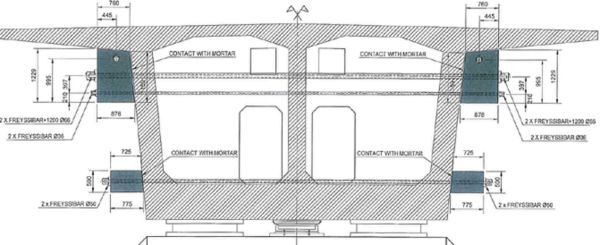
Freyssinet provides two 22T15S unit external PT tendons. They are positioned outside the box girder and run along the box-girder external webs (one on each side). They are deviated through concrete deviation blocks clamped in the box girder at piers and in spans.
At the location of the abutments, the additional PT was anchored in concrete blocks, clamped to the webs with PT Freyssibar. The abutment webs were strengthened for local bending and back-tie forces.
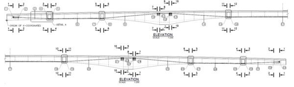
Kiegésíztő hosszirányú megerősítés elrendezése
The constraint regarding the layout of external PT was not to be lower than the bottom fiber of deck in order not to infringe within navigability clearance of the Té canal.
This constraint limited the flexural capacity of external PT.
For deck transverse strengthening, a solution combining both shotcrete and carbon rods has been designed to resist the additional bending moment in the overhangs.
Shotcrete-based solution was chosen in order to increase the lever arm of overhang by adding a concrete layer varying from 0.130m at edge to 0.250m at gusset. As shotcrete alone wasn’t sufficient to increase the bending capacity to the required demand, without increasing significantly the dead load, carbon rods are provided at the cantilever connection with the web, were bending moment is the most significant.
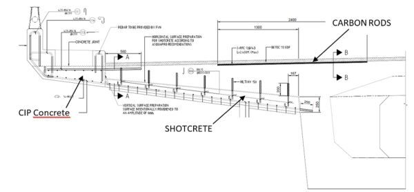
Pályalemez szélesítés séma
After being prepared similarly to the approaches, d12 carbon rods are installed in grooves made in the existing deck concrete. Bonding is ensured with the existing concrete using mortar.
The combination of the shotcrete and carbon rods increased the flexural capacity allowing to meet the SLS stress limitations in reinforcement steel which was the controlling design criteria for this part of the study.
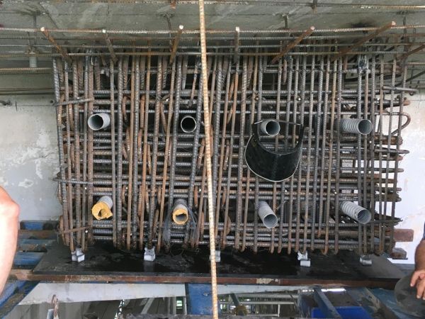
The diaphragms at pier were undergoing additional loads due the widening of the bridge. The additional loads were not only due to the permanent increase of the self-weight of the bridge due to its widening and strengthening by also to the additional applicable live load, compliant with the most recent Vietnamese specifications. An increase of shear and torsion had to be considered for the analysis of the diaphragms.
As it can be seen on the figure, the box girder is a three webs girders with the central web having two significant opening on each side, making the distribution of the force unfavorable and solicitating the bottom tie in the bottom slab above its capacity. In order to reduce the tension in the bottom tie, a third bearing is to be installed below the central web, allowing to directly transfer the loads from central web to the pier cap.
The bearing is active, as after installation it’s injected with a special epoxy product allowing it to be jacked and loaded at permanent state.
The top and bottom tie are strengthened using transverse PT bars as it can be seen on the figure bellow in order to bring the tension below allowable limits in the transverse tie.
Diafragma megerősítés
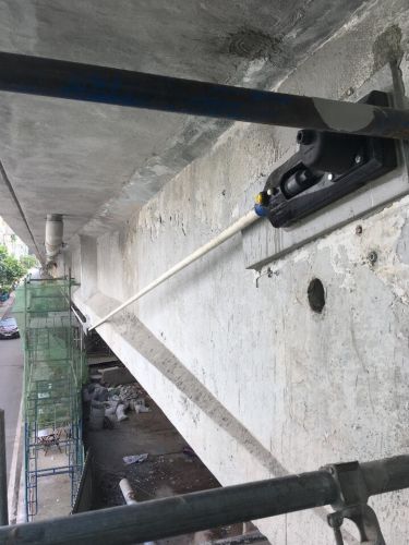
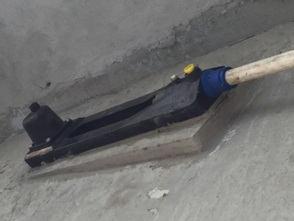
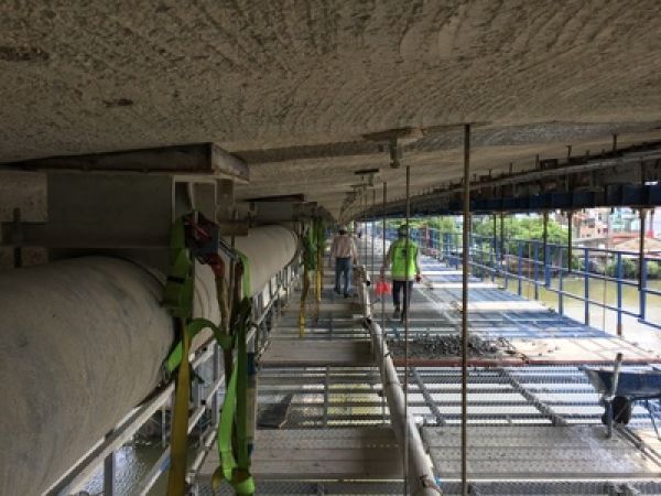
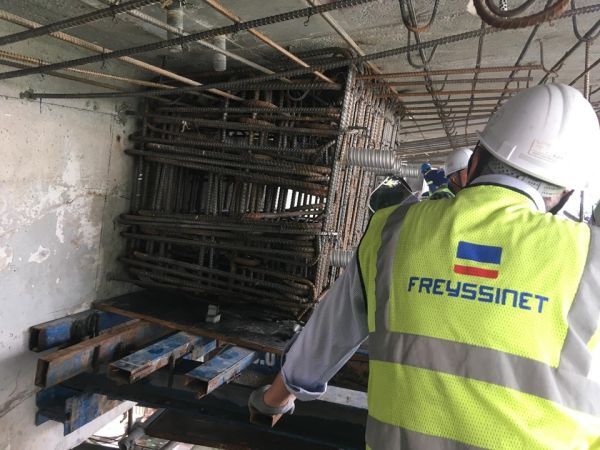
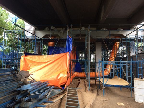
Minimizing of environmental impact is one of Freyssinet’s most important objectives, specially for urban projects. Sand blasting and shotcreting produce a significant amount of dust and have a negative impact on the environment, specially the nearby houses. These works have also a direct effect to the health of nozzlemen confined in the projection environment. To control this issue, HSE of site team has set up a comprehensive system including:
- PPE for nozzlemen with improved sealing and air supply
- Working zone is covered to avoid dust coming out
- Dust is collected by ventilation system and water
These arrangements allowed to reduce to a minimum the environmental and health impact of the Kenh-Te bridge widening works.
További hasznos anyagok találhatóak a letöltések menüpont alatt és szívesen állunk rendelkezésre elérhetőségeinken is az említett technológiákkal kapcsolatban.